INTRODUCTION TO THE KERNEL
The last chapter gave a high-level perspective of the UNIX system environment. This chapter focuses on the kernel, providing an overview of its architecture and outlining basic concepts and structures essential for understanding the rest of the book.
2.1 ARCHITECTURE OF THE UNIX OPERATING SYSTEM
It has been noted (see page 239 of [Christian 83]) that the UNIX system supports the illusions that the file system has “places” and that processes have “life.” The two entities, files and processes, are the two central concepts in the UNIX system model. Figure 2.1 gives a block diagram of the kernel, showing various modules and their relationships to each other. In particular, it shows the file subsystem on the left and the process control subsystem on the right, the two major components of the kernel. The diagram serves as a useful logical view of the kernel, although in practice the kernel deviates from the model because some modules interact with the internal operations of others.
Figure 2.1 shows three levels: user, kernel, and hardware. The system call and library interface represent the border between user programs and the kernel depicted in Figure 1.1. System calls look like ordinary function calls in C programs, and libraries map these function calls to the primitives needed to enter
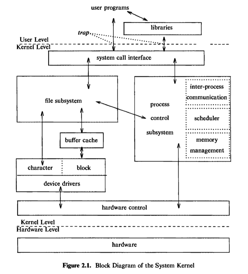
the operating system, as covered in more detail in Chapter 6. Assembly language programs may invoke system calls directly without a system call library, however. Programs frequently use other libraries such as the standard I/O library to provide a more sophisticated use of the system calls. The libraries are linked with the programs at compile time and are thus part of the user program for purposes of this discussion. An example later on will illustrate these points.
The figure partitions the set of system calls into those that interact with the file subsystem and those that interact with the process control subsystem. The file subsystem manages files, allocating file space, administering free space, controlling access to files, and retrieving data for users. Processes interact with the file subsystem via a specific set of system calls, such as open (to open a file for reading or writing), close、read, write, stat (query the attributes of a file), chown (change the record of who owns the file), and chmod (change the access permissions of a file). These and others will be examined in Chapter 5.
The file subsystem accesses file data using a buffering mechanism that regulates data flow between the kernel and secondary storage devices. The buffering mechanism interacts with block I/O device drivers to initiate data transfer to and from the kernel. Device drivers are the kernel modules that control the operation of peripheral devices. Block I/O devices are random access storage devices; alternatively, their device drivers make them appear to be random access storage devices to the rest of the system. For example, a tape driver may allow the kernel to treat a tape unit as a random access storage device. The file subsystem also interacts directly with “raw” I/O device drivers without the intervention of a buffering mechanism. Raw devices, sometimes called character devices, include all devices that are not block devices.
The process control subsystem is responsible for process synchronization, interprocess communication, memory management, and process scheduling. The file subsystem and the process control subsystem interact when loading a file into memory for execution, as will be seen in Chapter 7: the process subsystem reads executable files into memory before executing them.
Some of the system calls for controlling processes are fork (create a new process), exec (overlay the image of a program onto the running process), exit (finish executing a process), wait (synchronize process execution with the exit of a previously forked process), brk (control the size of memory allocated to a process), and signal (control process response to extraordinary events). Chapter 7 will examine these system calls and others.
The memory management module controls the allocation of memory. If at any time the system does not have enough physical memory for all processes, the kernel moves them between main memory and secondary memory so that all processes get a fair chance to execute. Chapter 9 will describe two policies for managing memory: swapping and demand paging. The swapper process is sometimes called the scheduler, because it “schedules” the allocation of memory for processes and influences the operation of the CPU scheduler. However, this text will refer to it as the swapper to avoid confusion with the CPU scheduler.
The scheduler module allocates the CPU to processes. It schedules them to run in turn until they voluntarily relinquish the CPU while awaiting a resource or until the kernel preempts them when their recent run time exceeds a time quantum. The scheduler then chooses the highest priority eligible process to run; the original process will run again when it is the highest priority eligible process available.
There are several forms of interprocess communication, ranging from asynchronous signaling of events to synchronous transmission of messages between processes.
Finally, the hardware control is responsible for handling interrupts and for communicating with the machine. Devices such as disks or terminals may interrupt the CPU while a process is executing. If so, the kernel may resume execution of the interrupted process after servicing the interrupt: Interrupts are not serviced by special processes but by special functions in the kernel, called in the context of the currently running process.
2.2 INTRODUCTION TO SYSTEM CONCEPTS
This section gives an overview of some major kernel data structures and describes the function of modules shown in Figure 2.1 in more detail.
2.2.1 An Overview of the File Subsystem
The internal representation of a file is given by an inode, which contains a description of the disk layout of the file data and other information such as the file owner, access permissions, and access times. The term inode is a contraction of the term index node and is commonly used in literature on the UNIX system. Every file has one inode, but it may have several names, all of which map into the inode. Each name is called a link. When a process refers to a file by name, the kernel parses the file name one component at a time, checks that the process has permission to search the directories in the path, and eventually retrieves the inode for the file. For example, if a process calls
1 | open("f2/mjb/rje/sourcefile", 1); |
the kernel retrieves the inode for “/fs2/mjb/rje/sourcefile”. When a process creates a new file, the kernel assigns it an unused inode. Inodes are stored in the file system, as will be seen shortly, but the kernel reads them into an in-core inode table when manipulating files.
The kernel contains two other data structures, the file table and the user file descriptor table. The file table is a global kernel structure, but the user file descriptor table is allocated per process. When a process opens or create a file, the kernel allocates an entry from each table, corresponding to the file’s inode. Entries in the three structures — user file descriptor table, file table, and inode table — maintain the state of the file and the user’s access to it. The file table keeps track of the byte offset in the file where the user’s next read or write will start, and the
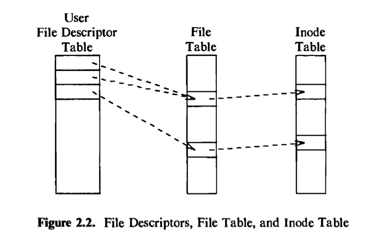
access rights allowed to the opening process. The user file descriptor table identifies all open files for a process. Figure 2.2 shows the tables and their relationship to each other. The kernel returns a file descriptor for the open and creat system calls, which is an index into the user file descriptor table. When executing read and write system calls, the kernel uses the file descriptor to access the user file descriptor table, follows pointers to the file table and inode table entries, and, from the inode, finds the data in the file. Chapters 4 and 5 describe these data structures in great detail. For now, suffice it to say that use of three tables allows various degrees of sharing access to a file.
The UNIX system keeps regular files and directories on block devices such as tapes or disks. Because of the difference in access time between the two, few, if any, UNIX system installations use tapes for their file systems. In coming years, diskless work stations will be common, where files are located on a remote system and accessed via a network (see Chapter 13). For simplicity, however, the ensuing text assumes the use of disks. An installation may have several physical disk units, each containing one or more file systems. Partitioning a disk into several file systems makes it easier for administrators to manage the data stored there. The kernel deals on a logical level with file systems rather than with disks, treating each one as a logical device identified by a logical device number. The conversion between logical device (file system) addresses and physical device (disk) addresses is done by the disk driver. This book will use the term device to mean a logical device unless explicitly stated otherwise.
A file system consists of a sequence of logical blocks, each containing 512, 1024, 2048, or any convenient multiple of 512 bytes, depending on the system implementation. The size of a logical block is homogeneous within a file system but may vary between different file systems in a system configuration. Using large logical blocks increases the effective data transfer rate between disk and memory, because the kernel can transfer more data per disk operation and therefore make fewer time-consuming operations. For example, reading IK bytes from a disk in one read operation is faster than reading 512 bytes twice. However, if a logical block is too large, effective storage capacity may drop, as will be shown in Chapter 5. For simplicity, this book will use the term “block” to mean a logical block, and it will assume that a logical block contains IK bytes of data unless explicitly stated otherwise.
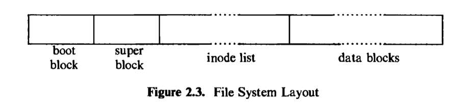
The boot block occupies the beginning of a file system, typically the first sector, and may contain the bootstrap code that is read into the machine to boot, or initialize, the operating system. Although only one boot block is needed to boot the system, every file system has a (possibly empty) boot block.
The super block describes the state of a file system — how large it is, how many files it can store, where to find free space on the file system, and other information.
The inode list is a list of inodes that follows the super block in the file system. Administrators specify the size of the inode list when configuring a file system. The kernel references inodes by index into the inode list. One inode is the root inode of the file system: it is the inode by which the directory structure of the file system is accessible after execution of the mount system call (Section 5.14).
The data blocks start at the end of the inode list and contain file data and administrative data. An allocated data block can belong to one and only one file in the file system.
2.2.2 Processes
This section examines the process subsystem more closely. It describes the structure of a process and some process data structures used for memory management. Then it gives a preliminary view of the process state diagram and considers various issues involved in some state transitions.
A process is the execution of a program and consists of a pattern of bytes that the CPU interprets as machine instructions (called “text”),data, and stack. Many processes appear to execute simultaneously as the kernel schedules them for execution, and several processes may be instances of one program. A process executes by following a strict sequence of instructions that is self-contained and does not jump to that of another process; it reads and writes its data and stack sections, but it cannot read or write the data and stack of other processes. Processes communicate with other processes and with the rest of the world via system calls.
In practical terms, a process on a UNIX system is the entity that is created by the fork system call. Every process except process 0 is created when another process executes the fork system calk The process that invoked the fork system call is the parent process, and the newly created process is the child process. Every process has one parent process, but a process can have many child processes. The kernel identifies each process by its process number, called the process ID (PID). Process 0 is a special process that is created *by hand, when the system boots; after forking a child process (process 1), process 0 becomes the swapper process. Process 1, known as init, is the ancestor of every other process in the system and enjoys a special relationship with them, as explained in Chapter 7.
A user compiles the source code of a program to create an executable file, which consists of several parts:
- a set of “headers” that describe the attributes of the file,
- the program text,
- a machine language representation of data that has initial values when the program starts execution, and an indication of how much space the kernel should allocate for uninitialized data, called bss1 (the kernel initializes it to 0 at run time),
- other sections, such as symbol table information.
For the program in Figure 1.3, the text of the executable file is the generated code for the functions main and copy , the initialized data is the variable version (put into the program just so that it should have some initialized data), and the uninitialized data is the array buffer. System V versions of the C compiler create a separate text section by default but support an option that allows inclusion of program instructions in the data section, used in older versions of the system.
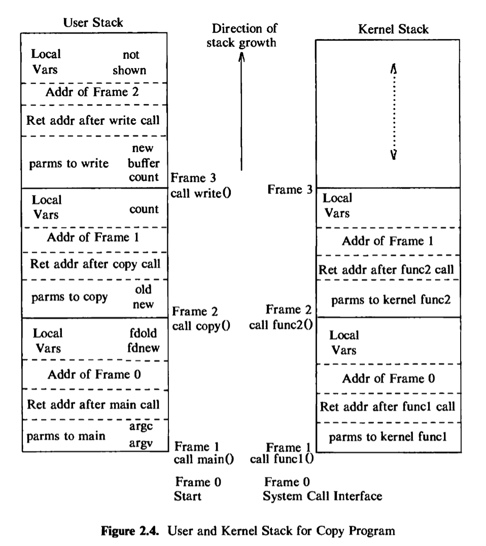
The kernel loads an executable file into memory during an exec system call, and the loaded process consists of at least three parts, called regions: text, data, and the stack. The text and data regions correspond to the text and data-bss sections of the executable file, but the stack region is automatically created and its size is dynamically adjusted by the kernel at run time. The stack consists of logical stack frames that are pushed when calling a function and popped when returning; a special register called the stack pointer indicates the current stack depth. A stack frame contains the parameters to a function, its local variables, and the data necessary to recover the previous stack frame, including the value of the program counter and stack pointer at the time of the function call. The program code contains instruction sequences that manage stack growth, and the kernel allocates space for the stack, as needed. In the program in Figure 1.3, parameters argc and argv and variables fdold and fdnew in the function main appear on the stack when main is called (once in every program, by convention), and parameters old and new and the variable count in the function copy appear on the stack whenever copy is called.
Because a process in the UNIX system can execute in two modes, kernel or user, it uses a separate stack for each mode. The user stack contains the arguments, local variables, and other data for functions executing in user mode. The left side of Figure 2.4 shows the user stack for a process when it makes the write system call in the copy program. The process startup procedure (included in a library) had called the function main with two parameters, pushing frame 1 onto the user stack; frame 1 contains space for the two local variables of main. Main then called copy with two parameters, old and new, and pushed frame 2 onto the user stack; frame 2 contains space for the local variable count. Finally, the process invoked the system call write by invoking the library function write. Each system call has an entry point in a system call library; the system call library is encoded in assembly language and contains special trap instructions, which, when executed, cause an “interrupt” that results in a hardware switch to kernel mode. A process calls the library entry point for a particular system call just as it calls any function, creating a stack frame for the library function. When the process executes the special instruction, it switches mode to the kernel, executes kernel code, and uses the kernel stack.
The kernel stack contains the stack frames for functions executing in kernel mode. The function and data entries on the kernel stack refer to functions and data in the kernel, not the user program, but its construction is the same as that of the user stack. The kernel stack of a process is null when the process executes in user mode. The right side of Figure 2.4 depicts the kernel stack representation for a process executing the write system call in the copy program. The names of the algorithms are described during the detailed discussion of the write system call in later chapters.
Every process has an entry in the kernel process table, and each process is allocated a u arec^ that contains private data manipulated only by the kernel. The process table contains (or points to) a per process region table, whose entries point to entries in a region table. A region is a contiguous area of a process’s address
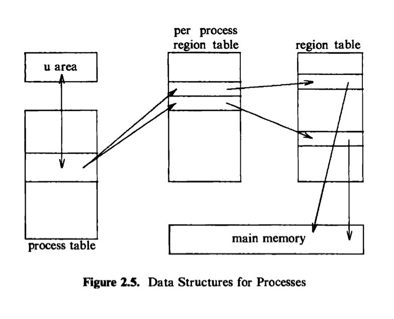
space, such as text, data, and stack. Region table entries describe the attributes of the region, such as whether it contains text or data, whether it is shared or private, and where the “data” of the region is located in memory. The extra level of indirection (from the per process region table to the region table) allows independent processes to share regions. When a process invokes the exec system call, the kernel allocates regions for its text, data, and stack after freeing the old regions the process had been using. When a process invokes fork, the kernel duplicates the address space of the old process, allowing processes to share regions when possible and making a physical copy otherwise. When a process invokes exit, the kernel frees the regions the process had used. Figure 2.5 shows the relevant data structures of a running process: The process table points to a per process region table with pointers to the region table entries for the text, data, and stack regions of the process.
The process table entry and the u area contain control and status information about the process. The u area is an extension of the process table entry, and Chapter 6 will examine the distinction between the two tables. Fields in the process table discussed in the following chapters are
- a state field,
- identifiers indicating the user who owns the process (user IDs, or UIDs),
- an event descriptor set when a process is suspended (in the sleep state).
The u area ccxitains information describing the process that needs to be accessible only when the process is executing. The important fields are
- a pointer to the process table slot of the currently executing process,
- parameters of the current system call, return values and error codes,
- file descriptors for all open Ales,
- internal I/O parameters,
- current directory and current root (see Chapter 5),
- process and file size limits.
The kernel can directly access Helds of the u area of the executing process but not of the u area of other processes. Internally, the kernel references the structure variable u to access the u area of the currently running process, and when another process executes, the kernel rearranges its virtual address space so that the structure u refers to the u area of the new process. The implementation gives the kernel an easy way to identify the current process by following the pointer from the u area to its process table entry.
2.2.2.1 Context of a process
The context of a process is its state, as defined by its text, the values of its global user variables and data structures, the values of machine registers it uses, the values stored in its process table slot and u area, and the contents of its user and kernel stacks. The text of the operating system and its global data structures are shared by all processes but do not constitute part of the context of a process.
When executing a process, the system is said to be executing in the context of the process. When the kernel decides that it should execute another process, it does a context switch, so that the system executes in the context of the other process. The kernel allows a context switch only under specihc conditions, as will be seen. When doing a context switch, the kernel saves enough information so that it can later switch back to the first process and resume its execution. Similarly, when moving from user to kernel mode, the kernel saves enough information so that it can later return to user mode and continue execution from where it left off. Moving between user and kernel mode is a change in mode, not a context switch. Recalling Figure 1.5, the kernel does a context switch when it changes context from process A to process B; it changes execution mode from user to kernel or from kernel to user, still executing in the context of one process, such as process A.
The kernel services interrupts in the context of the interrupted process even though it may not have caused the interrupt. The interrupted process may have been executing in user mode or in kernel mode. The kernel saves enough information so that it can later resume execution of the interrupted process and services the interrupt in kernel mode. The kernel does not spawn or schedule a special process to handle interrupts.
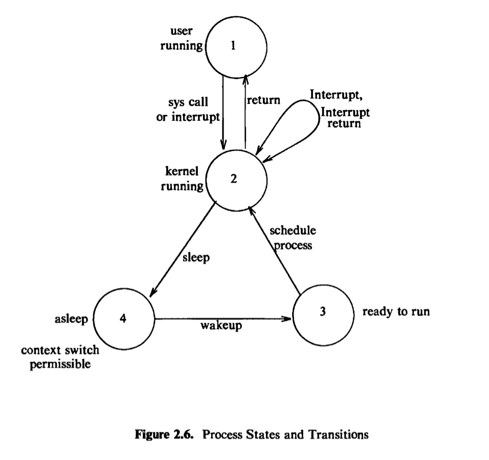
2.2.2.1 Process states
The lifetime of a process can be divided into a set of states*、*each with certain characteristics that describe the process. Chapter 6 will describe all process states, but it is essential to understand the following states now:
The process is currently executing in user mode.
The process is currently executing in kernel mode.
The process is not executing, but it is ready to run as soon as the scheduler chooses it. Many processes may be in this state, and the scheduling algorithm determines which one will execute next.
The process is sleeping. A process puts itself to sleep when it can no longer continue executing, such as when it is waiting for I/O to complete.
Because a processor can execute only one process at a time, at most one process may be in states 1 and 2. The two states correspond to the two modes of execution, user and kernel.
2.2.2.3 State transitions
The process states described above give a static view of a process, but processes move continuously between the states according to well-defined rules. A state transition diagram is a directed graph whose nodes represent the states a process can enter and whose edges represent the events that cause a process to move from one state to another. State transitions are legal between two states if there exists an edge from the first state to the second. Several transitions may emanate from a state, but a process will follow one and only one transition depending on the system event that occurs. Figure 2.6 shows the state transition diagram fbr the process states defined above.
Several processes can execute simultaneously in a time-shared manner, as stated earlier, and they may all run simultaneously in kernel mode. If they were allowed to run in kernel mode without constraint, they could corrupt global kernel data structures. By prohibiting arbitrary context switches and controlling the occurrence of interrupts, the kernel protects its consistency.
The kernel allows a context switch only when a process moves from the state “kernel running” to the state “asleep in memory.* Processes running in kernel mode cannot be preempted by other processes; therefore the kernel is sometimes said to be *non-preemptive, although the system does preempt processes that are in user mode. The kernel maintains consistency of its data structures because it is non-preemptive, thereby solving the mutual exclusion problem — making sure that critical sections of code are executed by at most one process at a time.
For instance, ccmsider the sample code in Figure 2.7 to put a data structure, whose address is in the pointer bpl*、onto a doubly linked list after the structure whose address is in *bp. If the system allowed a context switch while the kernel executed the code fragment, the following situation could occur. Suppose the
kernel executes the code until the comment and then does a context switch. The doubly linked list is in an inconsistent state: the structure bpl is half on and half off the linked list. If a process were to follow the forward pointers, it would find bpl on the linked list, but if it were to follow the back pointers, it would not find bpl (Figure 2.8). If other processes were to manipulate the pointers on the linked list before the original process ran again, the structure of the doubly linked list could be permanently destroyed. The UNIX system prevents such situations by disallowing context switches when a process executes in kernel mode. If a process goes to sleep, thereby permitting a context switch, kernel algorithms are encoded to make sure that system data structures are in a safe, consistent state.
A related problem that can cause inconsistency in kernel data is the handling of interrupts, which can change kernel state information. For example, if the kernel was executing the code in Figure 2.7 and received an interrupt when it reached the
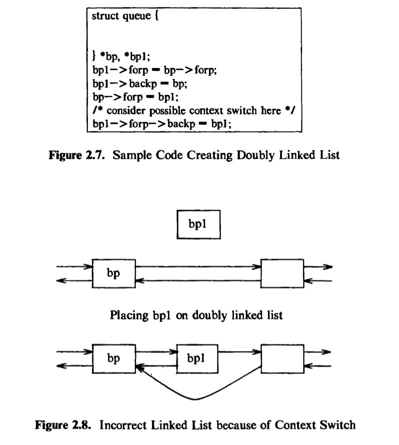
comment, the interrupt handler could corrupt the links if it manipulates the pointers, as illustrated earlier. To solve this problem, the system could prevent all interrupts while executing in kernel mode, but that would delay servicing of the interrupt, possibly hurting system throughput. Instead, the kernel raises the processor execution level to prevent interrupts when entering critical regions of code. A section of code is critical if execution of arbitrary interrupt handlers could result in consistency problems. For example, if a disk interrupt handler manipulates the buffer queues in the figure, the section of code where the kernel manipulates the buffer queues is a critical region of code with respect to the disk interrupt handler. Critical regions are small and infrequent so that system throughput is largely unaffected by their existence. Other operating systems solve this problem by preventing all interrupts when executing in system states or by using elaborate locking schemes to ensure consistency. Chapter 12 will return to this issue for multiprocessor systems, where the solution outlined here is insufficient.
To review, the kernel protects its consistency by allowing a context switch only when a process puts itself to sleep and by preventing one process from changing the state of another process. It also raises the processor execution level around critical regions of code to prevent interrupts that could otherwise cause inconsistencies. The process scheduler periodically preempts processes executing in user mode so that processes cannot monopolize use of the CPU.
2.2.2.4 Sleep and wakeup
A process executing in kernel mode has great autonomy in deciding what it is going to do in reaction to system events. Processes can communicate with each other and “suggest” various alternatives, but they make the final decision by themselves. As will be seen, there is a set of rules that processes obey when confronted with various circumstances, but each process ultimately follows these rules under its own initiative. For instance, when a process must temporarily suspend its execution (“go to sleep”), it does so of its own free will. Consequently, an interrupt handler cannot go to sleep, because if it could, the interrupted process would be put to sleep by default.
Processes go to sleep because they are awaiting the occurrence of some event, such as waiting for I/O completion from a peripheral device, waiting for a process to exit, waiting for system resources to become available, and so on. Processes are said to sleep on an event, meaning that they are in the sleep state until the event occurs, at which time they wake up and enter the state “ready to run.” Many processes can simultaneously sleep on an event; when an event occurs, all processes slewing on the event wake up because the event condition is no longer true. When a process wakes up, it follows the state transition from the “sleep” state to the “ready-to-run” state, where it is eligible for later scheduling; it does not execute immediately. Sleeping processes do not consume CPU resources: The kernel does not constantly check to see that a process is still sleeping but waits for the event to occur and awakens the process then.
For example, a process executing in kernel mode must sometimes lock a data structure in case it goes to sleep at a later stage; processes attempting to manipulate the locked structure must check the lock and sleep if another process owns the lock. The kernel implements such locks in the following manner:
1 | while (condition is true) |
It unlocks the lock and awakens all processes asleep on the lock in the following manner:
1 | set condition false; |
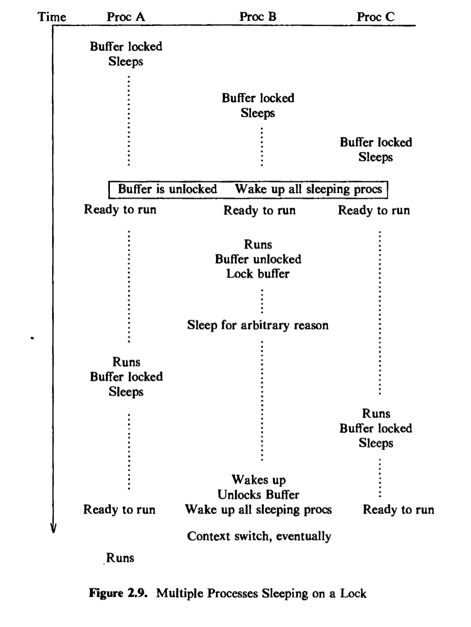
Figure 2.9 depicts a scenario where three processes, A, B, and C, contend for a locked buffer. The sleep condition is that the buffer is locked. The processes execute one at a time, find the buffer locked, and sleep on the event that the buffer becomes unlocked. Eventually, the buffer is unlocked, and all processes wake up and enter the state “ready to run.” The kernel eventually chooses one process, say B, to execute. Process B executes the “while” loop, finds that the buffer is unlocked, sets the buffer lock, and proceeds. If process B later goes to sleep again before unlocking the buffer (waiting for completion of an I/O operation, for example), the kernel can schedule other processes to run. If it chooses process A, process A executes the “while” loop, finds that the buffer is locked, and goes to sleep again; process C may do the same thing. Eventually, process B awakens and unlocks the buffer, allowing either process A or C to gain access to the buffer. Thus, the “while-sleep” loop insures that at most one process can gain access to a resource.
Chapter 6 will present the algorithms for sleep and wakeup in greater detail. In the meantime, they should be considered “atomic”: A process enters the sleep state instantaneously and stays there until it wakes up. After it goes to sleep, the kernel schedules another process to run and switches context to it.
2.3 KERNEL DATA STRUCTURES
Most kernel data structures occupy fixed-size tables rather than dynamically allocated space. The advantage of this approach is that the kernel code is simple, but it limits the number of entries for a data structure to the number that was originally configured when generating the system: If, during operation of the system, the kernel should run out of entries for a data structure, it cannot allocate space for new entries dynamically but must report an error to the requesting user. If, on the other hand, the kernel is configured so that it it is unlikely to run out of table space, the extra table space may be wasted because it cannot be- used for other purposes. Nevertheless, the simplicity of the kernel algorithms has generally been considered more important than the need to squeeze out every last byte of main memory. Algorithms typically use simple loops to find free table entries, a method that is easier to understand and sometimes more efficient than more complicated allocation schemes.
2.4 SYSTEM ADMINISTRATION
Administrative processes are loosely classified as those processes that do various functions for the general welfare of the user community. Such functions include disk formatting, creation of new file systems, repair of damaged file systems, kernel debugging, and others. Conceptually, there is no difference between administrative
processes and user processes: They use the same set of system calls available to the general community. They are distinguished from general user processes only in the rights and privileges they are allowed. For example, file permission modes may allow administrative processes to manipulate files otherwise off-limits to general users. Internally, the kernel distinguishes a special user called the superuser^ endowing it with special privileges, as will be seen. A user may become a superuser by going through a login-password sequence or by executing special programs. Other uses of superuser privileges will be studied in later chapters. In short, the kernel does not recognize a separate class of administrative processes.
2.5 SUMMARY AND PREVIEW
This chapter has described the architecture of the kernel; its two major components are the file subsystem and the process subsystem. The file subsystem controls the storage and retrieval of data in user files. Files are organized into file systems, which are treated as logical devices; a physical device such as a disk can contain several logical devices (file systems). Each file system has a super block that describes the structure and contents of the file system, and each file in a file system is described by an inode that gives the attributes of the file. System calls that manipulate files do so via inodes.
Processes exist in various states and move between them according to well- defined transition rules. In particular, processes executing in kernel mode can suspend their execution and enter the sleep state, but no process can put another process to sleep. The kernel is non-preemptive, meaning that a process executing in kernel mode will continue to execute until it enters the sleep state or until it returns to execute in user mode. The kernel maintains the consistency of its data structures by enforcing the policy of non-preemption and by blocking interrupts when executing critical regions of code.
The remainder of this text describes the subsystems shown in Figure 2.1 and their interactions in detail, starting with the file subsystem and continuing with the process subsystem. The next chapter covers the buffer cache and describes buffer allocation algorithms, used in the algorithms presented in Chapters 4, 5, and 7. Chapter 4 examines internal algorithms of the file system, including the manipulation of inodes, the structure of files, and the conversion of path names to inodes. Chapter 5 explains the system calls that use the algorithms in Chapter 4 to access the file system, such as open, close, read, and write. Chapter 6 deals with the basic ideas of the context of a process and its address space, and Chapter 7 covers system calls that deal with process management and use the algorithms in Chapter 6. Chapter 8 examines process scheduling, and Chapter 9 discusses memory management algorithms. Chapter 10 covers device drivers, postponed to this point so that the relationship between the terminal driver and process management can be explained. Chapter 11 presents several forms of interprocess communication. Finally, the last two chapters cover advanced topics, including multiprocessor systems and distributed systems.